Oxygen saving apparatus

Background

The 2nd wave of the COVID-19 virus has exposed a host of supply chain and production issues pertaining to medical oxygen. It is found that a fraction of oxygen during inhalation is actually inspired and the rest of the oxygen simply rejected into the atmosphere. In view of this, we have designed and tested an oxygen conservation device. The purpose of the document is to enable manufacturers and suppliers to develop an ecosystem for component supply and/or development of the entire product.

Process


PIC

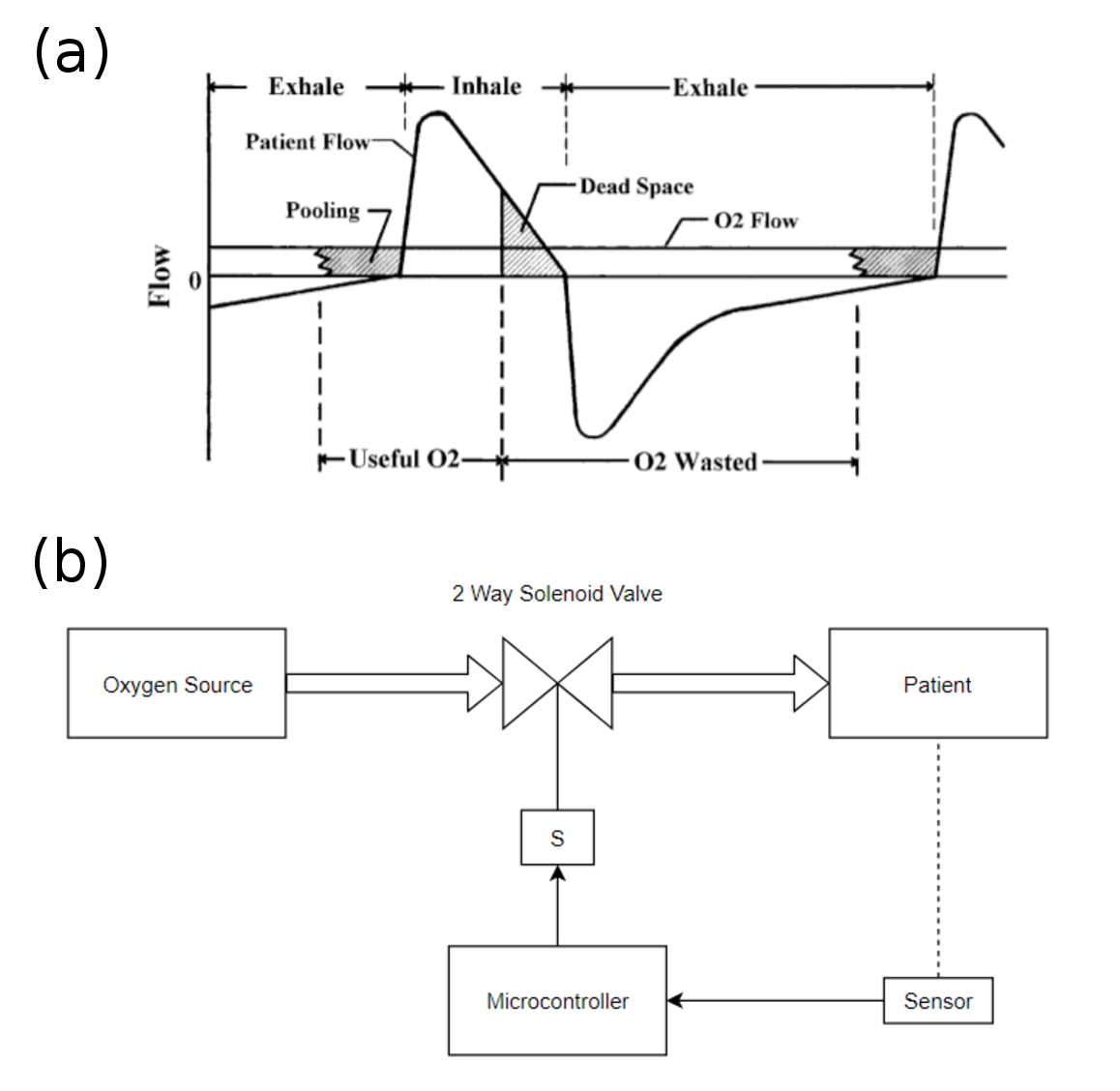
Figure 6: Diagram of a respiratory flow cycle in relation to a continuous flow of supplemental oxygen. The schematic of the process applied in this case.


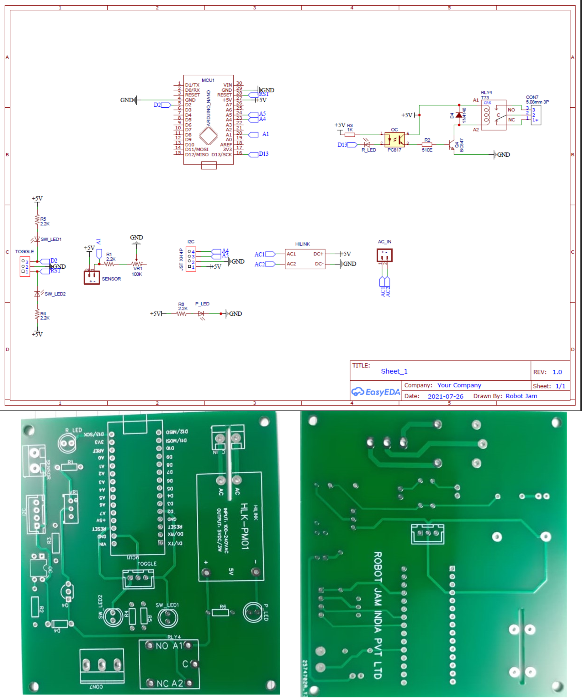
The device cuts off supply during exhalation but keeps the supply on during Inhalation and Pooling. A solenoid valve is connected in between the oxygen source (concentrator or cylinder) and the patient. The valve provides only digital control (either ON or OFF) and does not control the rate of flow oxygen. The solenoid valve is controlled by a microcontroller (Arduino). The microcontroller uses a Force Sensing Resistor like the FSR402 or FlexiForce A401 is used to capture the phase in which the breathing cycle is in. Accordingly the microprocessor switches the solenoid valve ON or OFF to stop or resume the flow of oxygen to the patient.

There are three states of the system, Pooling, Inhalation, Exhalation. Two states are identified, inhalation and exhalation. Pooling state is expected to begin at a fixed time before inhalation begins. This time-parameter can be tuned via code uploaded.

Quick setup

  1. Connect the solenoid valve into the Oxygen circuit, i.e. between the source and patient.
  2. Connect the two terminals of the Solenoid Valve to any one pair of the screw terminals present.
  3. Tie the belt with sensor housing around the chest of the patient, around the Solar Plexus. The belt should not be too tight nor too loose, similar to the belts tied around the waist.
  4. Tie the belt with sensor housing around the chest of the patient, around the Solar Plexus. The belt should not be too tight nor too loose, similar to the belts tied around the waist.
  5. Connect the AC mains (220V) to the other pair of the screw terminals. This is converted internally to 5V DC for use by the microcontroller and the sensor circuit. The mains is supplied via a relay to the solenoid Valve.
  6. Turn on the power supply. The Power ON LED should turn on immediately.
  7. There are two modes of operation, Full Flow and Controlled Flow. Full flow mode allows unrestricted flow of oxygen. Controlled flow stops and allows the flow of oxygen autonomously as explained before
  8. A toggle switch is present to change the modes. LEDs are present indicating location of the switch.
    To change to Controlled Flow, push the switch to Reset and then to the middle position.
    To change to Full Flow, push the switch to Full Flow and then to the middle position.
    The turning of switch to any one position is to record that a change is required by the user. The turning back to middle position is to implement the change. The time gap must be greater than 250ms between recording and implementing. The switch should not be left in positions other than the middle, as the state between recording and implementing the mode could behave unexpectedly.
  9. The Flow ON LED shall glow when the valve is set to allow flow of Oxygen.

    If this LED misbehaves, check if the toggle switch is in the middle position or not. If not, just toggle between the required Mode position and middle position.


PIC

Figure 7: The location of the solar plexus where the belt should be mounted. The 3d design of the belt is shown in the cad file. This houses the flex sensor which helps in identification of the breathing steps.


Construction

Pneumatics In order to maximize reliability, high quality pneumatics are desired, such as those manufactured by Festo. All the threaded connections are 1/4” BSP while all the push-fit connectors are for an 8mm OD tube. For convenience, we mention that the drill and tap size for the 1/4” BSP threads is 7/16” drill and G1/4” tap.

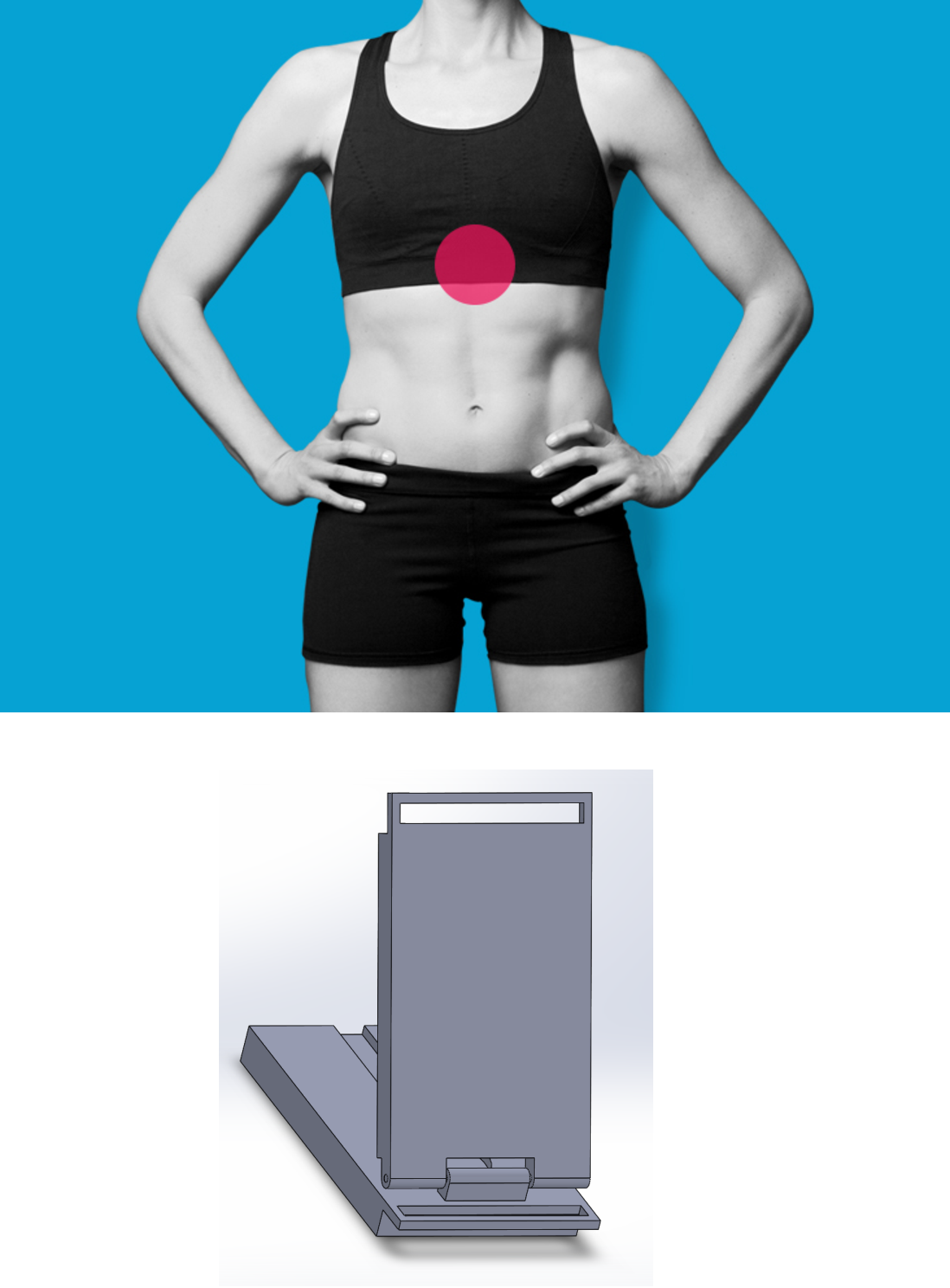
Sensors A force sensing resistor is encased in a sensor casing.

Slots are available in the casing to tie the casing to the belt. The belt should be tight enough to induce compression on the sensor but better sensitivity is achieved if the belt is as loose as possible.

The design was made according to dimensions of FSR406 but the size may be changed as required. Other sensors commonly available in market include FSR402 [2] and FlexiForce A401 may also be used. The resistances provided these are similar (100K   10K) and should be compatible.


PIC

Figure 8: Schematic of the circuit and the actual PCBs fabricated.


Processing: Arduino code for the Oxy-saver device

The arduino sketch provided here does not include any code for the OLED display and must be separately written by the user.

Bill of materials


Name QuantityPriceCost Remarks Link


Relay 1 20 20 https://www.roboelements.com/product/leone-5v-pcb-mount-spdt-sugar-cube-relay-switch/?gclid=CjwKCAjw9aiIBhA1EiwAJ_GTShXtlgwc45uNOIckX9DmMhx2QujFsY_aDTQdmTak0eY82kCwc1KGIRoCYhAQAvD_BwE


HiLink 5V 3W 1 229 229 To connect Supply to Arduino https://robu.in/product/hlk-pm01-5v-3w-switch-power-supply-module/


JST Connector Pair 2 7 14 To connect Potentiometer and Sensor to the Board Easily https://robu.in/product/2-pins-3-96mm-pitch-jst-vh-connector-with-housing-pack-of-10/


Toggle Switch 1 30 30 Change mode of operation https://robokits.co.in/automation-control-cnc/cnc-accessories/dpdt-rocker-momentary-switch?gclid=CjwKCAjw9aiIBhA1EiwAJ_GTSqVWuu7Sz3lLMcmM5AweXFbyFIO4tOGj-J9DSGCHGibkreNppxN-QhoCITkQAvD_BwE


Multi Turn 100k Pot1 18 18 https://robu.in/product/3296w-100k-ohm-trimpot-trimmer-potentiometer-pack-of-5/


Arduino Nano 1 399 399 If you do not have cable, https://robu.in/product/arduino-nano-board-r3-ch340-chip-with-usb-cable-solderedarduino-nano-r3-usb-cable/https://robu.in/product/arduino-nano-board-3-0-with-ch340-chip-unsoldered/


Wire 5 11.5 57.5 in m, As per requirement https://www.electroncomponents.com/twisted-2-wire-cable-14-76-power-mutlicolor-flexible?gclid=CjwKCAjw9aiIBhA1EiwAJ_GTSkKPe9m78BOE68dBvRE9BX5Uw2lKnVdW-AJSNCznIRyDUd7rU8R47BoCjN4QAvD_BwE


Heat Shrink 4 mm 1 19 19 in m, to cover the ends of sensors and any wires https://robu.in/product/heat-shrink-sleeve-4mm-transparent-2meter-industrial-grade-woer-hst/


Force Sensor 1 690 690 This one is same too https://www.robomart.com/force-sensing-resistor-0.5 https://robu.in/product/force-sensor-resistor-0-5-14-7mm-pressure-sensor/


Resistor 100 Ohm 4 1 4 https://robu.in/product/0-5w-100-ohm-resistor-pack-of-50/


Resistor 2.2 K 1 1 1 https://robu.in/product/2-2k-ohm-0-5w-metal-film-resistor-pack-of-50/


Resistor 1 K 1 1 1 https://www.electroncomponents.com/1k-ohm-resistance-1w-resistor?gclid=CjwKCAjw9aiIBhA1EiwAJ_GTSnDQs9Xb2P-GPuSsuDs8rwHoVeL6_VhPLlujtVw92T7d_dg7gDpHkhoCyacQAvD_BwE


Resistor 510 Ohm 1 0.7 0.7 https://quartzcomponents.com/products/510-ohm-1-4-watt-resistor-with-1-tolerance-pack-of-10?variant=35648479330457&currency=INR&utm_medium=product_sync&utm_source=google&utm_content=sag_organic&utm_campaign=sag_organic&utm_campaign=gs-2020-12-29&utm_source=google&utm_medium=smart_campaign&gclid=CjwKCAjw9aiIBhA1EiwAJ_GTSilKFkSsNHNrnUfaDbRqH6EdHeuoZdhZStySNP8_nL9CwNegEJ7zbRoCB5cQAvD_BwE


PC817 1 10 10 https://robu.in/product/pc817-dip-4-transistor-output-optocoupler-pack-of-5-ics/


LED 4 1 4 https://robu.in/product/5mm-red-dip-led-pack-of-50/


1N4148 Diode 1 2 2 https://robu.in/product/1n4148-1w-zener-diode-pack-of-50/


BC547 1 1.5 1.5 https://robu.in/product/bc547-npn-transistor-pack-of-20/


Solenoid Valve 1 799 799 Normally Open if possible https://robu.in/product/dc-12v-solenoid-valve-1-8-2-way-normally-closed-direct-pneumatic-valves-for-water-air-gas-hot/


Panel Box 1 100 100 Depends on Manufacturing


Total2399.7


Acknowledgments

The work at IIT Kharagpur has been undertaken by Sridhar Singhal (Dual Degree Student, Department of Electronics and Electrical Communication Engineering), Prof. Aditya Bandopadhyay (Mechanical Engineering Department), and Prof. Manoj Mondal (Rajendra Mishra School of Entrepreneurship). This work has been made possible through the generous and timely funding received from the IIT Foundation in USA in memory of AK Singh (Batch of 1993), and from Mrs. K. V. S. Jagdamba, wife of Prof. Mondal.

Refined PCB design and assembly by Robot Jam India Pvt. Ltd.

Disclaimer

Disclaimer of Medical Liability. WE, THE UNDERTAKERS OF THIS WORK ON OxyConserver Oxygen Conserving Device DESIGN AND MANUFACTURE, DO NOT PROVIDE MEDICAL ADVICE. The contents of the Site are for general informational purposes only. The content is not intended to be a substitute for professional medical advice, diagnosis, or treatment. Reliance on any information provided on the Sites is solely at your own risk. Individual medical needs are very different; you should not assume that the information on the Sites concerning certain courses of treatment or outcomes will apply to you. Rather, you should evaluate your medical condition and make treatment decisions based upon consultation with your physician.

The contents of the Sites may be of interest to medical professions or other health care providers. Medical professionals and health care providers should exercise their own judgment in determining whether a particular product or procedure is appropriate for their practice or their patients.

IIT Kharagpur and the makers of the OxyConserver Oxygen Conserving Device make no warranties, expressed or implied, including, but not limited to, any implied warranty of fitness of KGP-O2 oxygen concentrator except for usage for COVID 19 purposes and in accordance with the prescribed standards.

IIT Kharagpur and the makers of the OxyConserver Oxygen Conserving Device shall not be held responsible for for any inappropriate use and/ or misuse of the OxyConserver Oxygen Conserving Device by the user and any resultant effect/ impact/ injury.

References and Resources

[1] : https://c.aarc.org/marketplace/reference_articles/01.00.0095.pdf Oxygen-Conserving Techniques and Devices - Robert McCoy

[2] : https://www.trossenrobotics.com/productdocs/2010-10-26-DataSheet-FSR402-Layout2.pdf FSR402 Sensor Datasheet

[3] : https://www.dropbox.com/sh/l9vke1e2y8kvcgx/AADlQ-4gCFAzl0BPA0Cfjfiia?dl=0 - PCB File

[4] : https://www.dropbox.com/sh/f23xz7vmfuxrdae/AADDFMEtvmck43ycXjM376Pya?dl=0- Sensor Casing CAD files

[5] : https://github.com/sridhar-singhal/oxy_saver GitHub Repository